Calibration#
1. Purpose / Scope#
This application demonstrates the procedure to calibrate the carrier frequency offset, Tx gain offset and few more parameters and update them to the Flash/Efuse. Customers need to calibrate these two parameters on their platforms after chip integration.
2. Prerequisites / Setup Requirements#
Before running the application, the user will need the following things to setup.
2.1 Hardware Requirements#
Windows PC with Host interface (UART/ SPI).
Silicon Labs RS9116 Wi-Fi Evaluation Kit
Host MCU Eval Kit. This example has been tested with:
Silicon Labs WSTK + EFR32MG21
Spectrum Analyzer
RF Cable connects between EVK and Spectrum Analyzer.
2.2 Software Requirements#
Embedded Development Environment.
For STM32, use licensed Keil IDE
For Silicon Labs EFx32, use the latest version of Simplicity Studio.
Python 3 installation
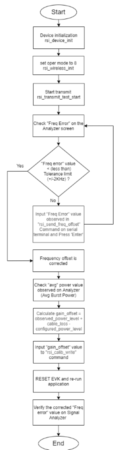
2.3 Flowchart for Calibration Process#
3. Application Build Environment#
3.1 Platform#
The Application can be built and executed on below Host platforms
3.2 Host Interface#
By default, the application is configured to use the SPI bus for interfacing between Host platforms and the RS9116W EVK.
The SAPI driver provides APIs to enable other host interfaces if SPI is not suitable for your needs.
3.3 Project Configuration#
The Application is provided with the project folder containing Keil and Simplicity Studio project files.
Keil Project
The Keil project is used to evaluate the application on STM32.
Project path:
<SDK>/examples/snippets/wlan/calibration_app/projects/calibration_app-nucleo-f411re.uvprojx
Simplicity Studio
The Simplicity Studio project is used to evaluate the application on EFR32MG21.
Project path:
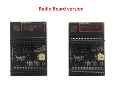
If the Radio Board is BRD4180A or BRD4181A, then access the path
<SDK>/examples/snippets/wlan/calibration_app/projects/calibration_app-brd4180a-mg21.slsprojIf the Radio Board is BRD4180B or BRD4181B, then access the path
<SDK>/examples/snippets/wlan/calibration_app/projects/calibration_app-brd4180b-mg21.slsprojUser can find the Radio Board version as given below
3.4 Bare Metal Support#
This application supports only bare metal environment. By default, the application project files (Keil and Simplicity studio) are provided with bare metal configuration in the SDK.
4. Application Configuration Parameters#
The application can be configured to suit user requirements and development environment. Read through the following sections and make any changes needed.
4.1 Open rsi_calib_app.c file. The desired parameters are provided below. User can also modify the parameters as per their needs and requirements.#
To set TX power in dBm. The valid values are from 2dbm to 18dbm for WiSeConnectTM module.
#define RSI_TX_TEST_POWER 18To set transmit data rate.
#define RSI_TX_TEST_RATE RSI_RATE_1To configure length of the TX packet. Valid values are in the range of 24 to 1500 bytes in the burst mode and range of 24 to 260 bytes in the continuous mode.
#define RSI_TX_TEST_LENGTH 1000 To configure Burst mode or Continuous mode
#define RSI_TX_TEST_MODE RSI_BURST_MODETo configure the channel number in 2.4 GHz or 5GHz. Here mention the channel number. For example user wants to given channel 1 in 2.4 GHz
#define RSI_TX_TEST_CHANNEL 1To select internal antenna or UFL connector
#define RSI_ANTENNA 0Note: RSI_ANTENNA value should be set to 0 for Single Band module and 1 for Dual Band module
To select antenna gain in db for 2.4GHz band. Valid values are from 0 to 10.
#define RSI_ANTENNA_GAIN_2G 0To select antenna gain in db for 5GHz band. Valid values are from 0 to 10.
#define RSI_ANTENNA_GAIN_5G 04.2 Open rsi_wlan_config.h file. User can also modify the below parameters as per their needs and requirements.#
#define CONCURRENT_MODE RSI_DISABLE
#define RSI_FEATURE_BIT_MAP FEAT_SECURITY_OPEN
#define RSI_TCP_IP_BYPASS RSI_DISABLE
#define RSI_TCP_IP_FEATURE_BIT_MAP TCP_IP_FEAT_DHCPV4_CLIENT
#define RSI_CUSTOM_FEATURE_BIT_MAP 0
#define RSI_BAND RSI_BAND_2P4GHZ5. Testing the Application#
Follow the steps below for the successful execution of the application.
5.1 Loading the RS9116W Firmware#
Refer Getting started with a PC to load the firmware into RS9116W EVK. The firmware file is located in <SDK>/firmware/
5.2 Building the Application on Host Platform#
5.2.1 Using STM32#
Refer Getting started with STM32
Open the project
<SDK>/examples/snippets/wlan/calibration_app/projects/calibration_app-nucleo-f411re.uvprojxBuild and Debug the project
Check for the RESET pin:
If RESET pin is connected from STM32 to RS9116W EVK, then user need not press the RESET button on RS9116W EVK before free run.
If RESET pin is not connected from STM32 to RS9116W EVK, then user need to press the RESET button on RS9116W EVK before free run.
Free run the project
Then continue the common steps from 5.3
5.2.2 Using EFX32#
Refer Getting started with EFX32
Open Simplicity Studio and import the project from
<SDK>/examples/snippets/wlan/calibration_app/projectsSelect the appropriate .slsproj as per the Radio Board type mentioned in Section 3.3
Compile and flash the project in to Host MCU
Debug the project
Check for the RESET pin:
If RESET pin is connected from STM32 to RS9116W EVK, then user need not press the RESET button on RS9116W EVK before free run
If RESET pin is not connected from STM32 to RS9116W EVK, then user need to press the RESET button on RS9116W EVK before free run
Free run the project
Then continue the common steps from 5.3
5.3 Common Steps#
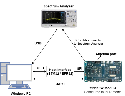
Make connections as per setup diagram (above) and set the appropriate settings on the Spectrum Analyzer by using the steps mentioned in below Spectrum Analyzer Settings.
After the program gets executed, the RS9116W device will start the transmit test with the given configuration.
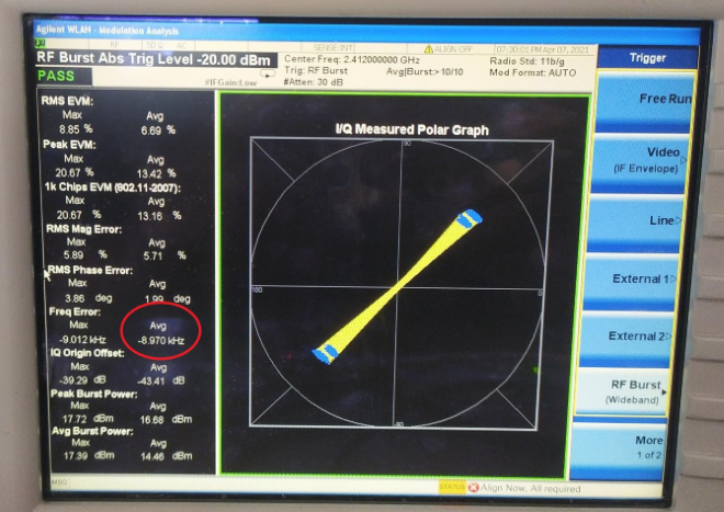
Refer the below image which shows when RS9116W device transmits packets in Burst mode with different Tx power and different transmission rates in channel 1 with length 1000bytes.
RSI_TX_TEST_POWER - 18dBm RSI_TX_TEST_RATE - 1Mbps RSI_TX_TEST_LENGTH - 1000 RSI_TX_TEST_MODE - BURST mode RSI_TX_TEST_CHANNEL - 1Observe the Avg Freq Error (highlighted) on the screen and now try to adjust the frequency offset by using CLI commands with serial terminal (Docklight or Teraterm)
Frequency Offset Correction#
Frequency offset correction will be done by using the rsi_freq_offset command. This command is used during the RF calibration process and requires PER mode transmissions to be initiated prior. This command sends freq_offset (deviation) as observed on the signal analyzer against the expected channel frequency.
Prototype :
rsi_freq_offset = freq_offset_in_khz <CR><LF>Here freq_offset_in_khz means Frequency deviation in KHz or ppm
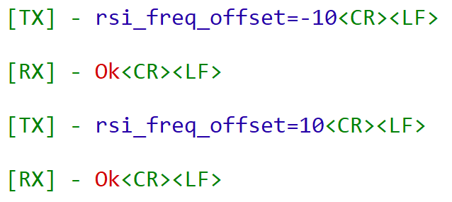
Examples :
rsi_freq_offset=10<CR><LF>
rsi_freq_offset=-10<CR><LF>
Note: User can use the above command for any number of times till it gets tuned to desired frequency offset.
Open the serial terminal (Docklight/TeraTerm tool) and enter the following commands. User can provide input to correct frequency offset by sending the commands on console. This should lead towards a correction in the frequency offset as observed earlier and repeat till the error is within the tolerance limits (+/- 2 KHz tolerance limits).
See the below picture after frequency offset correction.
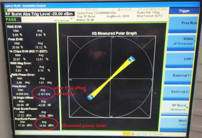
Note: freq_offset_in_khz can be either +ve or -ve. When user enters the freq offset as observed on signal analyzer (+ve/-ve), a small freq offset correction is done. User needs to iterate this till the freq offset is within tolerance limits.
Gain Offset Correction:#
Update XO Ctune and Gain Offset#
Using rsi_calib_write command the calibrated XO Ctune and calculated gain offset can be updated to target memory (Flash/Efuse).
Prototype :
rsi_calib_write=<target>,<flags>,<gain_offset>,<xo_ctune>Gain offset can be calculated using the following equation :
gain_offset = observed_power_level + cable_loss - configured_power_level
Example :
gain_offset = 14.3 + 1.7 (assuming) - 18 = -2 dBm
This command writes to Flash, gain offset as -2 dBm and XO Ctune value as it reads from hardware.
To update gain offset as -2 dBm and xo ctune as per the value in hardware register into flash use the command below.
rsi_calib_write=1,3,-2 <CR><LF>
NOTE : The gain_offset can be negative but not a floating value. Once the frequency offset is corrected after multiple tries, rsi_calib_write commands has to be given once for all to write the values to flash.
Parameters
Parameter | Description | ||
|---|---|---|---|
target | Value | Macro | Description |
0 | BURN_INTO_EFUSE | Burns calibration data to EFuse | |
1 | BURN_INTO_FLASH | Burns calibration data to Flash | |
flags | BIT | Macro | Description |
0 | BURN_GAIN_OFFSET | 1 - Update gain offset to calibration data | |
0 - Skip gain offset update | |||
1 | BURN_FREQ_OFFSET | 1 - Update XO Ctune to calibration data | |
0 - Skip XO Ctune update | |||
2 | SW_XO_CTUNE_VALID | 1- Use XO Ctune provided as argument to update calibration data | |
0 -Use XO Ctune value as read from hardware register. | |||
7 -3 | Reserved | ||
gain_offset | gain offset as observed in dBm | ||
xo_ctune | This field allows user to directly update xo_ctune \n value to calibration data bypassing the freq \n offset loop, valid only when \n BURN_FREQ_OFFSET & SW_XO_CTUNE_VALID \n of flags is set. |
Precondition: rsi_freq_offset command needs to be called before this command when xo ctune value from hardware register is to be used.
Spectrum Analyzer Settings#
Below are setting necessary to see Polar Graph Spectrum Analyzer settings
Frequency channel → center frequency→ 2412MHz for channel1.
SpanX scale → span→ 50MHz
Mode → WLAN → Mode setup → Radio Std → 802.11a/b/g → 802.11 b/g
Trigger → RF Burst
The frequency error section shows the amount of error that needs to be adjusted. Using freq_offset API and Calib_write API user should be able to adjust the frequency error.
Acronyms and Abbreviations#
Acronym | Description |
|---|---|
TX | Transmit |
RX | Receive |
RF | Radio Frequency |
WLAN | Wireless Local Area Network |
XO | Crystal Oscillator |
Ctune | Captune |
Q7 | Single band RS9116 EVK |
A7 | Dual band RS9116 EVK |